
What Is a Continuity Test?
A Continuity Test is an electrical check that determines whether a complete, low-resistance path exists between two points in a circuit. A meter or dedicated tester sends a small test signal through the path and indicates continuity when the connection is complete. The result helps identify open wires, loose connections, broken conductors, or closed switches.
Quick Facts About Continuity Test
Category
Electrical diagnostic test
Used for
Finding open or broken circuit paths
Common confusion
A continuity reading is not a voltage reading
Also called
Continuity check, Circuit Continuity Test
Often discussed with
Electrical Troubleshooting
Key Takeaways About Continuity Test
- It checks for an unbroken electrical path.
- A positive reading does not measure operating voltage.
- Continuity is not the same as circuit power.
How Continuity Test Works
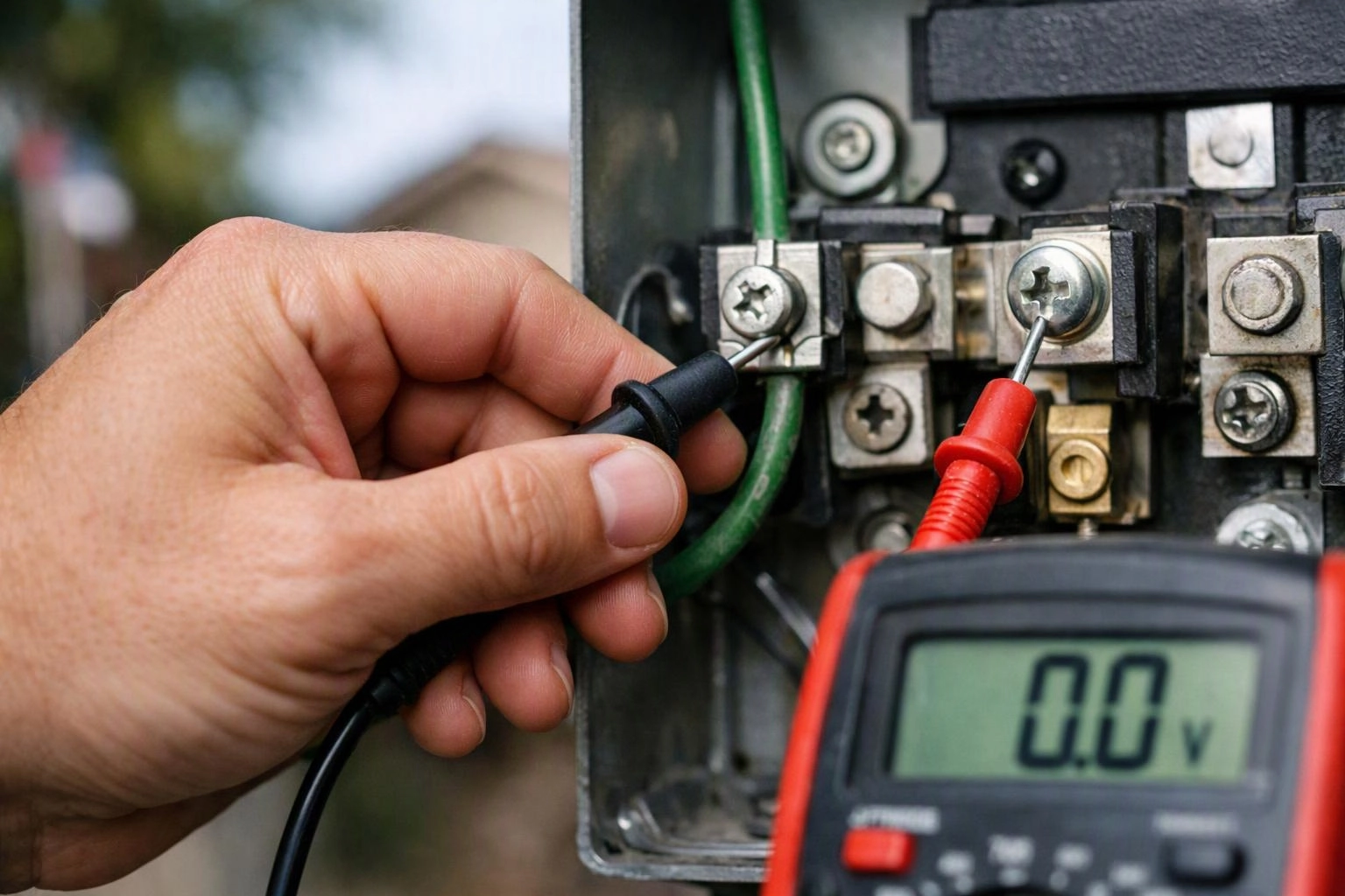
A Continuity Test uses a multimeter or continuity tester to send a small signal between two contact points. The instrument detects whether the signal completes its path and may show a tone, a display indication, or a resistance reading. A complete path usually points to connected conductors, while an open result directs attention to a break or disconnected point.
Related glossary terms: Multimeter, Short Circuit, Electrical Grounding.
The test is performed on a de-energized circuit because the instrument is checking the circuit path itself. A technician may test a wire end to end, a switch in different positions, or a protective conductor between connection points. Resistance and multimeter readings can add detail when a simple tone does not explain the condition. The result guides further troubleshooting, but it does not show how the circuit behaves under operating load.
From the Center Electric Service team
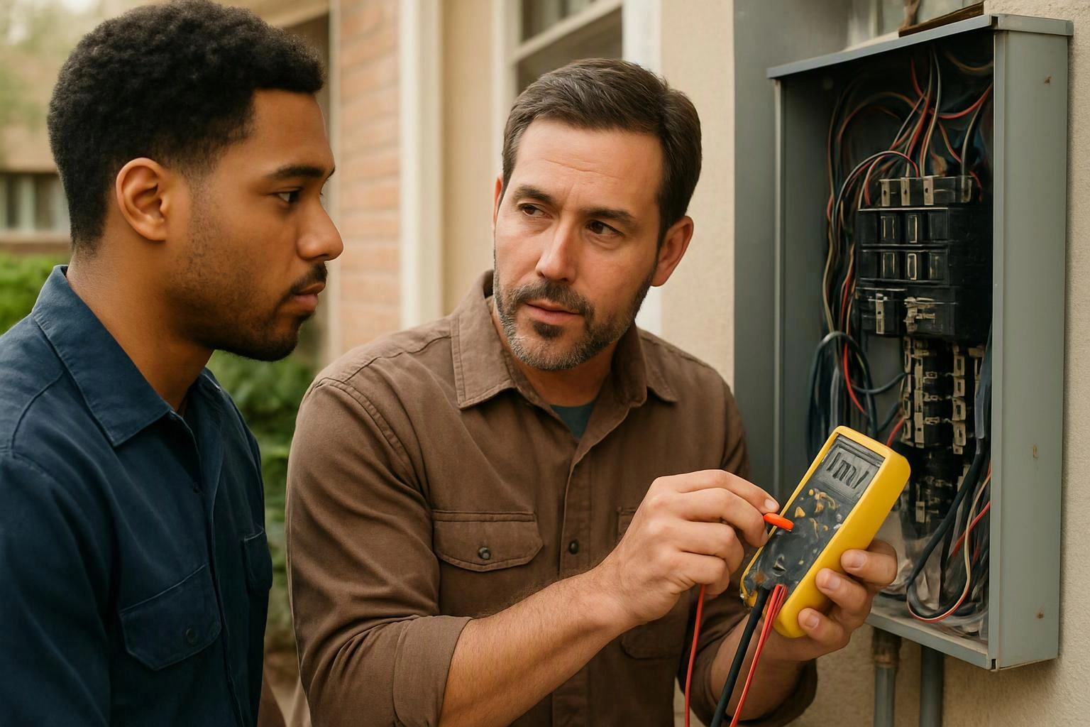
When we troubleshoot a circuit, we isolate the relevant conductors and check continuity across suspected breaks, switches, and connection points. We compare the reading with the circuit layout and inspect terminals when the result does not match the expected path. This helps us separate an open circuit from a power or load problem.
Continuity Test in Practice: A Real-World Example
A wall receptacle may appear dead because a conductor has loosened inside a junction box. During electrical troubleshooting, a continuity test across the disconnected conductor can show whether the wire path remains intact, helping direct the inspection toward the connection point.
Related Services
Related Terms
Multimeter
A multimeter is a handheld electrical test instrument that measures voltage, current, and resistance. Many models…
Short Circuit
Short Circuit is an unintended electrical connection that creates a low-resistance path between points with different…
Electrical Grounding
Electrical grounding is a protective connection between an electrical system and the earth or another approved…
Voltage Drop
Voltage Drop is the reduction in electrical pressure that occurs as current travels through a conductor…
Center Electric Service
Have Questions About Continuity Test?
Contact Center Electric Service for practical guidance on Continuity Test and related electrical services work in Riverside.